New Arrival China Replicating Bypass Switches - Mylinking™ Network Tap Bypass Switch ML-BYPASS-100 – Mylinking
New Arrival China Replicating Bypass Switches - Mylinking™ Network Tap Bypass Switch ML-BYPASS-100 – Mylinking Detail:
Overviews
Mylinking™ Network Tap Bypass Switch is researched and developed to be used for flexible deployment of various types of inline security equipment while providing high network reliability.
By deploying Mylinking™ Smart Bypass Switch Tap:
- Users can flexibly install/uninstall security equipment/tools and will not affect and interrupt the current network;
- Mylinking™ Network Tap Bypass Switch with intelligent health detection function to real-time monitoring of the normal working state of the inline security devices. Once the inline security devices work exception, the protection function will automatically bypass to maintain the normal network communication;
- Selective traffic protection technology can be used to deploy specific traffic cleaning security equipment, encryption technology based on the audit equipment. Effectively carry out the inline access protection for the specific traffic type, unloading the flow handling pressure of the inline device;
- Load Balanced Traffic Protection technology can be used for clustered deployment of secure serial inline security devices to meet the inline security in high-bandwidth environments.

Network Tap Bypass Switch Advanced Features & Technologies
Mylinking™ “SpecFlow” Protection Mode and “FullLink” Protection Mode
Mylinking™ Fast Bypass Switching Protection
Mylinking™ “LinkSafeSwitch”
Mylinking™ “WebService” Dynamic Strategy Forwarding/Issue
Mylinking™ Intelligent Heartbeat Message Detection
Mylinking™ Definable Heartbeat Messages(Heartbeat Packets)
Mylinking™ Multi-link Load Balancing
Mylinking™ Intelligent Traffic Distribution
Mylinking™ Dynamic Load Balancing
Mylinking™ Remote Management Technology(HTTP/WEB, TELNET/SSH, “EasyConfig/AdvanceConfig” Characteristic)
Network Tap Bypass Switch Optional Configuration Guide
BYPASS Module Protection Port Module Slot:
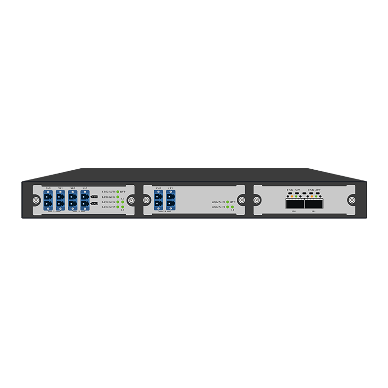
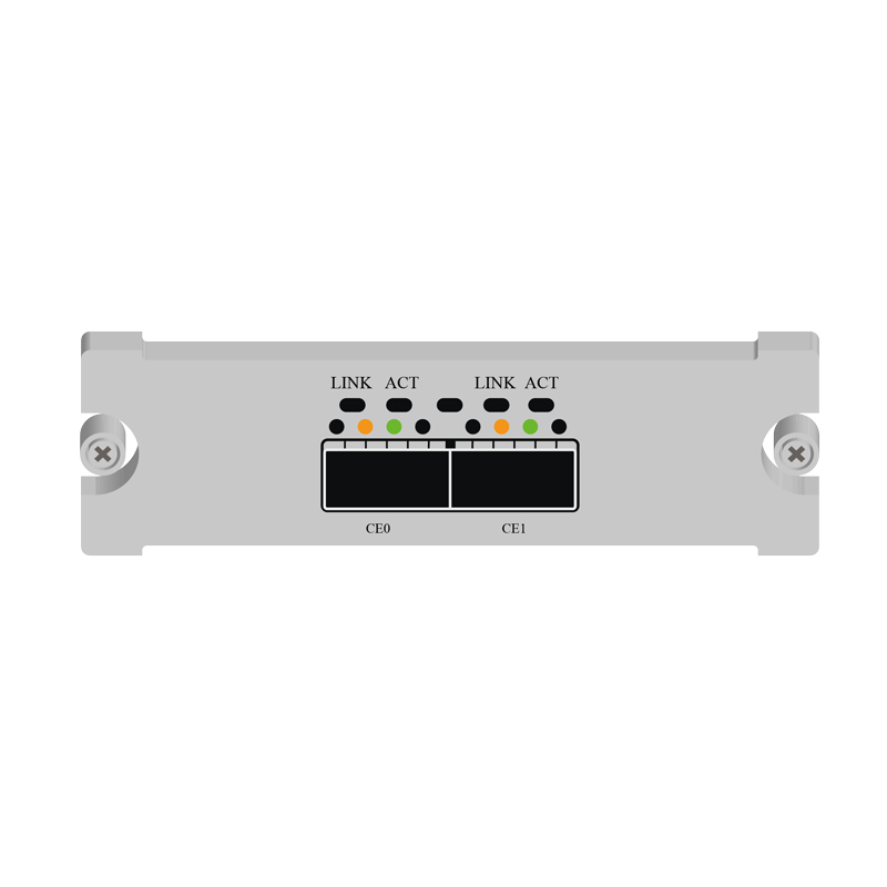
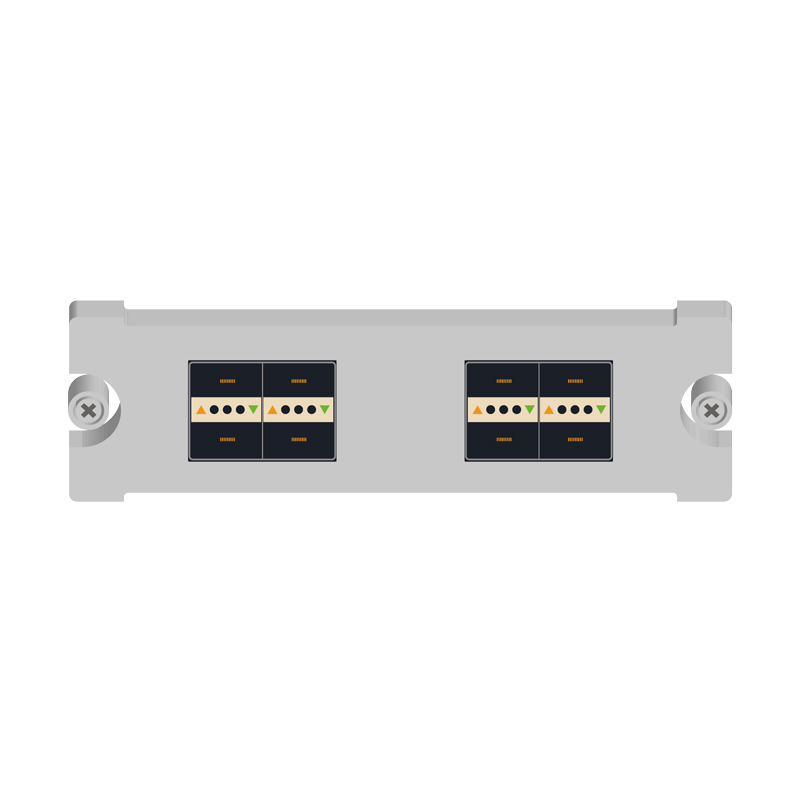
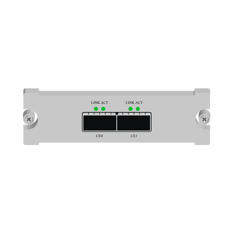
This slot can be inserted into BYPASS protection port module with different speed/port number. By replacing different types of modules, it can support BYPASS protection of multiple 10G/40G/100G links requirements.


MONITOR Module Port Module Slot;
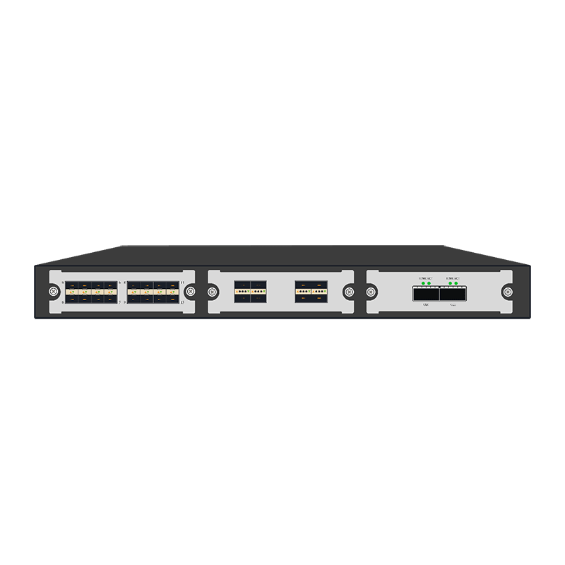
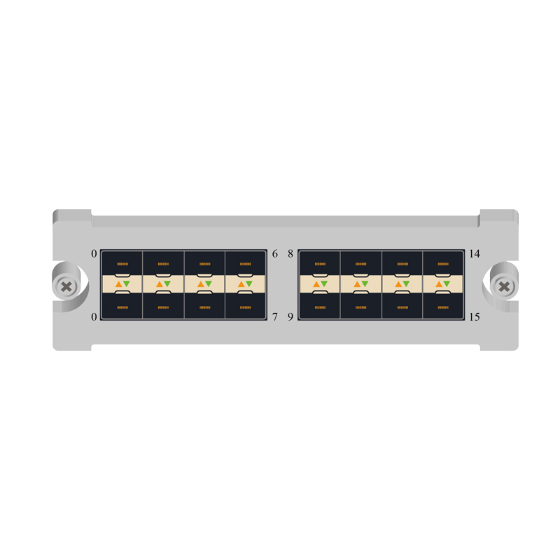
This slot can be inserted the MONITOR module with different speeds/ports. It can support multiple links of 10G/40G/100G for inline serial monitoring device deployment by replacing different modules.

Module Selection Rules
Based on different deployed links and monitoring equipment deployment requirements, you can flexibly choose different module configurations to meet your actual environment request; please follow the following rules during your module selecting:
1. The chassis components are mandatory and you must select the chassis components before you select any other modules. At the same time, please choose different power supply methods (AC/DC) according to your needs.
2. The whole device supports up to 2 BYPASS module slots and 1 MONITOR module slot; you can’t select more than the number of slots to configure. Based on the combination of the number of slots and the module model, the device can support up to four 10GE link protections; or it can support up to four 40GE links; or it can support up to one 100GE link.
3. The module model “BYP-MOD-L1CG” can only be inserted into SLOT1 to work properly.
4. The module type “BYP-MOD-XXX” can only be inserted into the BYPASS module slot; the module type “MON-MOD-XXX” can only be inserted into the MONITOR module slot for normal operation.
|
Product Model |
Function parameters |
|
Chassis(Host) |
|
| ML-BYPASS-M100 | 1U standard 19-inch rackmount; maximum power consumption 250W; modular BYPASS protector host; 2 BYPASS module slots; 1 MONITOR module slot; AC and DC optional; |
|
BYPASS MODULE |
|
| BYP-MOD-L2XG(LM/SM) | Supports 2-way 10GE link serial protection, 4*10GE interface, LC connector; built-in optical transceiver; optical link single/multimode optional, supports 10GBASE-SR/ LR; |
| BYP-MOD-L2QXG(LM/SM) | Supports 2-way 40GE link serial protection, 4*40GE interface, LC connector; built-in optical transceiver; optical link single/multimode optional, supports 40GBASE-SR4/ LR4; |
| BYP-MOD-L1CG (LM/SM) | Supports 1 channel 100GE link serial protection, 2*100GE interface, LC connector; built-in optical transceiver; optical link single multimode optional, supports 100GBASE-SR4/LR4 ; |
|
MONITOR MODULE |
|
| MON-MOD-L16XG | 16*10GE SFP+ monitoring port module; no optical transceiver module; |
| MON-MOD-L8XG | 8*10GE SFP+ monitoring port module; no optical transceiver module; |
| MON-MOD-L2CG | 2*100GE QSFP28 monitoring port module; no optical transceiver module; |
| MON-MOD-L8QXG | 8* 40GE QSFP+ monitoring port module; no optical transceiver module; |
Network TAP Bypass Switch Specifications
|
Product Modality |
ML-BYPASS-M100 Inline Network Tap Bypass Switch |
|
|
Type of Interface |
MGT Interface |
1*10/100/1000BASE-T Adaptive management interface; Support remote HTTP/IP management |
| Module Slot |
2*BYPASS module slot;1*MONITOR module slot; |
|
| Links supporting maximum |
Device support maximum 4*10GE links or 4*40GE links or 1*100GE links |
|
| Monitoring | Device support maximum 16*10GE monitoring ports or 8*40GE monitoring ports or 2*100GE monitoring ports; | |
|
Function |
Full duplex processing ability |
640Gbps |
| Based on IP/protocol/port five tuple specific traffic cascade protecting |
Supported |
|
| Cascade protection based on full traffic |
Supported |
|
| Multiple load balancing |
Supported |
|
| Custom heartbeat detecting function |
Supported |
|
| Support Ethernet package independence |
Supported |
|
| BYPASS SWITCH |
Supported |
|
| BYPASS Switch without flash |
Supported |
|
| CONSOLE MGT |
Supported |
|
| IP/WEB MGT |
Supported |
|
| SNMP V1/V2C MGT |
Supported |
|
| TELNET/SSH MGT |
Supported |
|
| SYSLOG protocol |
Supported |
|
| User authorization |
Based on password authorization/AAA/TACACS+ |
|
|
Electrical |
Rated supply voltage |
AC-220V/DC-48V【Optional】 |
| Rated power frequency |
50HZ |
|
| Rated input current |
AC-3A / DC-10A |
|
| Rated Power |
100W |
|
|
Environment |
Working Temperature |
0-50℃ |
| Storage temperature |
-20-70℃ |
|
| Working humidity |
10%-95%, No condensation |
|
|
User configuration |
Console configuration |
RS232 interface,115200,8,N,1 |
| Out of band MGT interface |
1*10/100/1000M Ethernet interface |
|
| Password authorization |
Supported |
|
|
Chassis Height |
Chassis space(U) |
1U 19 inch,485mm*44.5mm*350mm |
Network TAP Bypass Switch Application(as following)
5.1 The Risk of Inline Security Equipment (IPS / FW)
The following is a typical IPS (Intrusion Prevention System), FW (Firewall) deployment mode, IPS / FW is deployed as inline network equipment (such as routers, switches, etc.) between the traffic through the implementation of security checks, according to the corresponding security policy to determine the release or blocking the corresponding traffic, to achieve the effect of security defense.

At the same time, we can observe IPS(Intrusion Prevention System) / FW(Firewall) as a inline deployment of the equipment, usually deployed in the key location of the enterprise network to implement inline security, the reliability of its connected devices directly affect the overall enterprise network availability. Once the inline security devices overload, crash, software updates, policy updates, etc., the entire enterprise network availability will be greatly affected. At this point, we only through the network cut, physical bypass jumper can make the network to be restored, but it’s seriously affecting the reliability of the network. IPS(Intrusion Prevention System) / FW(Firewall) and other inline devices on one hand improve the deployment of enterprise network security, on the other hand also reduces the reliability of enterprise networks, increasing the risk of the network is not available.
5.2 Inline Link Series Equipment Protection

Mylinking™ ” Bypass Switch ” is deployed as inline between network devices (routers, switches, etc.), and the data flow between network devices no longer leads directly to IPS(Intrusion Prevention System) / FW(Firewall), ” Bypass Switch ” to IPS / FW, when the IPS / FW due to overload, crash, software updates, policy updates and other conditions of failure, the “Bypass Switch” through intelligent heartbeat message detection Function of the timely discovery, and thus skip the faulty device, without interrupting the premise of the network, the rapid network equipment directly connected to protect the normal communication network; when the IPS / FW failure recovery, but also through intelligent Heartbeat Packets Detection of timely detection of the function, the original link to restore the security of enterprise network security checks.
Mylinking™ “Bypass Switch” has a powerful intelligent Heartbeat Message Detection function, the user can customize the heartbeat interval and the maximum number of retries, through a custom heartbeat message on the IPS / FW for health testing, such as send the heartbeat check message to the upstream / downstream port of IPS / FW, and then receive from the upstream / downstream port of IPS / FW, and judge whether the IPS / FW is working normally by sending and receiving the heartbeat message.
5.3 “SpecFlow” Policy Flow Inline Traction Series Protection

When the security network device only needs to deal with the specific traffic in series security protection, through the Mylinking™ “ Network Tap Bypass Switch ” traffic per-processing function, through the traffic screening strategy to connect the security device ” Concerned “traffic is sent back directly to the network link, and the” concerned traffic section “is traction to the in-line safety device to perform safety checks. This will not only maintain the normal application of the safety detection function of the safety device, but also reduce the inefficient flow of the safety equipment to deal with the pressure; at the same time, the “ Network Tap Bypass Switch ” can detect the working condition of the safety device in real time. The safety device works abnormally bypasses the data traffic directly to avoid disruption of network service.
The Mylinking™ Inline Traffic Bypass Tap can identify traffic based on the L2-L4 layer header identifier, such as VLAN tag, source / destination MAC address, source IP address, IP packet type, transport layer protocol port, protocol header key tag, and so on. A variety of matching conditions flexible combination can be defined flexibly to define the specific traffic types that are of interest to a particular security device and can be widely used for the deployment of special security auditing devices (RDP, SSH, database auditing, etc.).
5.4 Load balanced Series Protection

The Mylinking™ “Network Tap Bypass Switch” is deployed as inline between network devices (routers, switches, etc.). When a single IPS / FW processing performance is not sufficient to cope with network link peak traffic, The traffic load balancing function of the protector, the “bundling” of multiple IPS / FW cluster processingnetwork link traffic, can effectively reduce the single IPS / FW processing pressure, improve the overall processing performance to meet the high bandwidth of the deployment environment Claim.
Mylinking™ “Network Tap Bypass Switch” has a powerful load balancing function, according to the frame VLAN tag, MAC information, IP information, port number, protocol and other information on the Hash load balancing distribution of traffic to ensure that each IPS / FW received data flow Session integrity.
5.5 Multi-series Inline Equipment Flow Traction Protection (Change Serial Connection to Parallel Connection)
In some key links (such as Internet outlets, server area exchange link) location is often due to the needs of security features and the deployment of multiple in-line security testing equipment (such as firewall(FW), anti-DDOS attack equipment, WEB Application Firewall(WAF), Intrusion Prevention System(IPS), etc.), multiple security detection equipment at the same time in series on the link to increase the link of a single point of failure, reducing the overall reliability of the network. And in the above-mentioned security equipment on-line deployment, equipment upgrades, equipment replacement and other operations, will cause the network for a long time service interruption and a larger project cut action to complete the successful implementation of such projects.
By deploying the “Network Tap Bypass Switch” in a unified manner, the deployment mode of multiple security devices connected in series on the same link can be changed from “physical concatenation mode” to “physical concatenation, logical concatenation mode” The link on the link of a single point of failure to improve the reliability of the link, while the “bypass switch” on the link flow on demand traction, to achieve the same flow with the original mode of safe processing effect.
More than one security device at the same time as inline deployment diagram:

Mylinking™ Network TAP Bypass Switch Deployment Diagram:

5.6 Based on the Dynamic Strategy of Traffic Traction Security Detection Protection
“Network Tap Bypass Switch” Another advanced application scenario is based on the dynamic strategy of traffic traction security detection protection applications, the deployment of the way as shown below:

Take the “Anti-DDoS attack protection and detection” security testing equipment, for example, through the front-end deployment of “ Network Tap Bypass Switch ” and then anti-DDOS protection equipment and then connected to the “ Network Tap Bypass Switch “, in the usual ” Traction protector “to the full amount of traffic wire-speed forwarding at the same time the flow mirror output to the” anti-DDOS attack protection device “, once detected for a server IP (or IP network segment) after the attack,” anti-DDOS attack protection device ” will generate the target traffic flow matching rules and send them to the “ Network Tap Bypass Switch ” through the dynamic policy delivery interface. The “ Network Tap Bypass Switch ” can update the “traffic traction dynamic” after receiving the dynamic policy rules Rule pool “and immediately” rule hit the attack server traffic “traction to the” anti-DDoS attack protection and detection “equipment for processing, to be effective after the attack flow and then re-injected into the network.
The application scheme based on the “ Network Tap Bypass Switch ” is easier to implement than the traditional BGP route injection or other traffic traction scheme, and the environment is less dependent on the network and the reliability is higher.
“Network Tap Bypass Switch” has the following characteristics to support dynamic policy security detection protection:
1, “ Network Tap Bypass Switch ” to provide outside the rules based on WEBSERIVCE interface, easy integration with third-party security devices.
2, ” BNetwork Tap Bypass Switch ” based on the hardware pure ASIC chip forwarding up to 10Gbps wire-speed packets without blocking switch forwarding, and “traffic traction dynamic rule library” regardless of the number.
3, ” Network Tap Bypass Switch” built-in professional BYPASS function, even if the protector itself failure, can also bypass the original serial link immediately, does not affect the original link of normal communication.
Product detail pictures:
Related Product Guide:
We also supply merchandise sourcing and flight consolidation companies. We now have our very own manufacturing facility and sourcing business. We could present you with almost every kind of product relevant to our solution array for New Arrival China Replicating Bypass Switches - Mylinking™ Network Tap Bypass Switch ML-BYPASS-100 – Mylinking , The product will supply to all over the world, such as: Libya, Honduras, Austria, We set a strict quality control system. We have return and exchange policy, and you can exchange within 7 days after receive the wigs if it is in new station and we service repairing free for our products. Please feel free to contact us for further information if you have any questions. We are glad to work for every client.
This is the first business after our company establish, products and services are very satisfying, we have a good start, we hope to cooperate continuous in the future!

